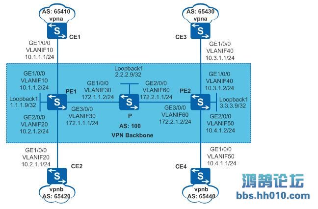
配置BGP/MPLS IP VPN示例BGP/MPLS IP VPN简介BGP/MPLS IP VPN是一种基于MPLS的L3VPN,组网方式灵活,可扩展性好,支持大规模部署。新增一个站点时,只需要修改提供该站点业务的边缘节点的配置。BGP/MPLS IP VPN适用于位于不同地理位置的公司总部和分支之间需要相互通信的场景,由于通信数据需要穿越运营商的骨干网,可以使用BGP在骨干网上发布VPN路由,使用MPLS在骨干网上转发VPN报文;由于公司内部各个部门之间需要相互隔离,可以通过该功能实现不同VPN之间的路由隔离、地址空间隔离和访问隔离。组网需求如图1所示:CE1连接公司总部研发区、CE3连接分支机构研发区,CE1和CE3属于vpna;CE2连接公司总部非研发区、CE4连接分支机构非研发区,CE2和CE4属于vpnb。公司要求通过部署BGP/MPLS IP VPN,实现总部和分支机构的安全互通,同时要求研发区和非研发区间数据隔离。图1 BGP/MPLS IP VPN组网图
配置思路采用如下的思路配置BGP/MPLS IP VPN:P、PE之间配置OSPF,实现骨干网的IP连通性。PE、P上配置MPLS基本能力和MPLS LDP,建立MPLS LSP公网隧道,传输VPN数据。PE1和PE2之间配置MP-IBGP,交换VPN路由信息。PE1和PE2上配置VPN实例,其中,vpna使用的VPN-target属性为111:1,vpnb使用的VPN-target属性为222:2,以实现相同VPN间互通,不同VPN间隔离。同时,与CE相连的接口和相应的VPN实例绑定,以接入VPN用户。CE与PE之间配置EBGP,交换VPN路由信息。操作步骤在MPLS骨干网上配置IGP协议,实现骨干网PE和P的互通# 配置PE1。<HUAWEI> system-view[HUAWEI] sysname PE1[PE1] interface loopback 1[PE1-LoopBack1] ip address 1.1.1.9 32[PE1-LoopBack1] quit[PE1] vlan batch 10 20 30[PE1] interface gigabitethernet 1/0/0[PE1-GigabitEthernet1/0/0] port link-type trunk[PE1-GigabitEthernet1/0/0] port trunk allow-pass vlan 10[PE1-GigabitEthernet1/0/0] quit[PE1] interface gigabitethernet 2/0/0[PE1-GigabitEthernet2/0/0] port link-type trunk[PE1-GigabitEthernet2/0/0] port trunk allow-pass vlan 20[PE1-GigabitEthernet2/0/0] quit[PE1] interface gigabitethernet 3/0/0[PE1-GigabitEthernet3/0/0] port link-type trunk[PE1-GigabitEthernet3/0/0] port trunk allow-pass vlan 30[PE1-GigabitEthernet3/0/0] quit[PE1] interface vlanif 30[PE1-Vlanif30] ip address 172.1.1.1 24[PE1-Vlanif30] quit[PE1] ospf 1 router-id 1.1.1.9[PE1-ospf-1] area 0[PE1-ospf-1-area-0.0.0.0] network 172.1.1.0 0.0.0.255[PE1-ospf-1-area-0.0.0.0] network 1.1.1.9 0.0.0.0[PE1-ospf-1-area-0.0.0.0] quit[PE1-ospf-1] quit# 配置P。<HUAWEI> system-view[HUAWEI] sysname P[P] interface loopback 1[P-LoopBack1] ip address 2.2.2.9 32[P-LoopBack1] quit[P] vlan batch 30 60[P] interface gigabitethernet 1/0/0[P-GigabitEthernet1/0/0] port link-type trunk[P-GigabitEthernet1/0/0] port trunk allow-pass vlan 30[P-GigabitEthernet1/0/0] quit[P] interface gigabitethernet 2/0/0[P-GigabitEthernet2/0/0] port link-type trunk[P-GigabitEthernet2/0/0] port trunk allow-pass vlan 60[P-GigabitEthernet2/0/0] quit[P] interface vlanif 30[P-Vlanif30] ip address 172.1.1.2 24[P-Vlanif30] quit[P] interface vlanif 60[P-Vlanif60] ip address 172.2.1.1 24[P-Vlanif60] quit[P] ospf 1 router-id 2.2.2.9[P-ospf-1] area 0[P-ospf-1-area-0.0.0.0] network 172.1.1.0 0.0.0.255[P-ospf-1-area-0.0.0.0] network 172.2.1.0 0.0.0.255[P-ospf-1-area-0.0.0.0] network 2.2.2.9 0.0.0.0[P-ospf-1-area-0.0.0.0] quit[P-ospf-1] quit# 配置PE2。<HUAWEI> system-view[HUAWEI] sysname PE2[PE2] interface loopback 1[PE2-LoopBack1] ip address 3.3.3.9 32[PE2-LoopBack1] quit[PE2] vlan batch 40 50 60[PE2] interface gigabitethernet 1/0/0[PE2-GigabitEthernet1/0/0] port link-type trunk[PE2-GigabitEthernet1/0/0] port trunk allow-pass vlan 40[PE2-GigabitEthernet1/0/0] quit[PE2] interface gigabitethernet 2/0/0[PE2-GigabitEthernet2/0/0] port link-type trunk[PE2-GigabitEthernet2/0/0] port trunk allow-pass vlan 50[PE2-GigabitEthernet2/0/0] quit[PE2] interface gigabitethernet 3/0/0[PE2-GigabitEthernet3/0/0] port link-type trunk[PE2-GigabitEthernet3/0/0] port trunk allow-pass vlan 60[PE2-GigabitEthernet3/0/0] quit[PE2] interface vlanif 60[PE2-Vlanif60] ip address 172.2.1.2 24[PE2-Vlanif60] quit[PE2] ospf 1 router-id 3.3.3.9[PE2-ospf-1] area 0[PE2-ospf-1-area-0.0.0.0] network 172.2.1.0 0.0.0.255[PE2-ospf-1-area-0.0.0.0] network 3.3.3.9 0.0.0.0[PE2-ospf-1-area-0.0.0.0] quit[PE2-ospf-1] quit配置完成后,PE1和P、P和PE2之间应能建立OSPF邻居关系,执行display ospf peer命令可以看到邻居状态为Full。执行display ip routing-table命令可以看到PE之间学习到对方的Loopback1路由。以PE1的显示为例:[PE1] display ip routing-tableRoute Flags: R - relay, D - download to fib------------------------------------------------------------------------------Routing Tables: Public Destinations : 8 Routes : 8 Destination/Mask Proto Pre Cost Flags NextHop Interface 1.1.1.9/32 Direct 0 0 D 127.0.0.1 LoopBack1 2.2.2.9/32 OSPF 10 1 D 172.1.1.2 Vlanif30 3.3.3.9/32 OSPF 10 2 D 172.1.1.2 Vlanif30 127.0.0.0/8 Direct 0 0 D 127.0.0.1 InLoopBack0 127.0.0.1/32 Direct 0 0 D 127.0.0.1 InLoopBack0 172.1.1.0/24 Direct 0 0 D 172.1.1.1 Vlanif30 172.1.1.1/32 Direct 0 0 D 127.0.0.1 Vlanif30 172.2.1.0/24 OSPF 10 2 D 172.1.1.2 Vlanif30[PE1] display ospf peer OSPF Process 1 with Router ID 1.1.1.9 NeighborsArea 0.0.0.0 interface 172.1.1.1(Vlanif30)'s neighborsRouter ID: 2.2.2.9 Address: 172.1.1.2 State: Full Mode:Nbr is Master Priority: 1 DR: 172.1.1.2 BDR: 172.1.1.1 MTU: 0 Dead timer due in 37 sec Retrans timer interval: 5 Neighbor is up for 00:16:21 Authentication Sequence: [ 0 ]在MPLS骨干网上配置MPLS基本能力和MPLS LDP,建立LDP LSP# 配置PE1。[PE1] mpls lsr-id 1.1.1.9[PE1] mpls[PE1-mpls] quit[PE1] mpls ldp[PE1-mpls-ldp] quit[PE1] interface vlanif 30[PE1-Vlanif30] mpls[PE1-Vlanif30] mpls ldp[PE1-Vlanif30] quit# 配置P。[P] mpls lsr-id 2.2.2.9[P] mpls[P-mpls] quit[P] mpls ldp[P-mpls-ldp] quit[P] interface vlanif 30[P-Vlanif30] mpls[P-Vlanif30] mpls ldp[P-Vlanif30] quit[P] interface vlanif 60[P-Vlanif60] mpls[P-Vlanif60] mpls ldp[P-Vlanif60] quit# 配置PE2。[PE2] mpls lsr-id 3.3.3.9[PE2] mpls[PE2-mpls] quit[PE2] mpls ldp[PE2-mpls-ldp] quit[PE2] interface vlanif 60[PE2-Vlanif60] mpls[PE2-Vlanif60] mpls ldp[PE2-Vlanif60] quit上述配置完成后,PE1与P、P与PE2之间应能建立LDP会话,执行display mpls ldp session命令可以看到显示结果中Status项为“Operational”。执行display mpls ldp lsp命令,可以看到LDP LSP的建立情况。以PE1的显示为例:[PE1] display mpls ldp sessionLDP Session(s) in Public NetworkCodes: LAM(Label Advertisement Mode), SsnAge Unit(DDDD:HH:MM)A '*' before a session means the session is being deleted.------------------------------------------------------------------------------PeerID Status LAM SsnRole SsnAge KASent/Rcv------------------------------------------------------------------------------2.2.2.9:0 Operational DU Passive 0000:00:01 6/6------------------------------------------------------------------------------TOTAL: 1 session(s) Found.[PE1] display mpls ldp lspLDP LSP Information-------------------------------------------------------------------------------Flag after Out IF: (I) - LSP Is Only Iterated by RLFA-------------------------------------------------------------------------------DestAddress/Mask In/OutLabel UpstreamPeer NextHop OutInterface -------------------------------------------------------------------------------1.1.1.9/32 3/NULL 2.2.2.9 127.0.0.1 InLoop0 *1.1.1.9/32 Liberal/1024 DS/2.2.2.92.2.2.9/32 NULL/3 - 172.1.1.2 Vlanif30 2.2.2.9/32 1024/3 2.2.2.9 172.1.1.2 Vlanif30 3.3.3.9/32 NULL/1025 - 172.1.1.2 Vlanif30 3.3.3.9/32 1025/1025 2.2.2.9 172.1.1.2 Vlanif30 -------------------------------------------------------------------------------TOTAL: 5 Normal LSP(s) Found.TOTAL: 1 Liberal LSP(s) Found.TOTAL: 0 Frr LSP(s) Found.A '*' before an LSP means the LSP is not establishedA '*' before a Label means the USCB or DSCB is staleA '*' before a UpstreamPeer means the session is staleA '*' before a DS means the session is staleA '*' before a NextHop means the LSP is FRR LSP在PE设备上配置VPN实例,将CE接入PE# 配置PE1。[PE1] ip vpn-instance vpna[PE1-vpn-instance-vpna] route-distinguisher 100:1[PE1-vpn-instance-vpna-af-ipv4] vpn-target 111:1 both[PE1-vpn-instance-vpna-af-ipv4] quit[PE1-vpn-instance-vpna] quit[PE1] ip vpn-instance vpnb[PE1-vpn-instance-vpnb] route-distinguisher 100:2[PE1-vpn-instance-vpnb-af-ipv4] vpn-target 222:2 both[PE1-vpn-instance-vpnb-af-ipv4] quit[PE1-vpn-instance-vpnb] quit[PE1] interface vlanif 10[PE1-Vlanif10] ip binding vpn-instance vpna[PE1-Vlanif10] ip address 10.1.1.2 24[PE1-Vlanif10] quit[PE1] interface vlanif 20[PE1-Vlanif20] ip binding vpn-instance vpnb[PE1-Vlanif20] ip address 10.2.1.2 24[PE1-Vlanif20] quit# 配置PE2。[PE2] ip vpn-instance vpna[PE2-vpn-instance-vpna] route-distinguisher 200:1[PE2-vpn-instance-vpna-af-ipv4] vpn-target 111:1 both[PE2-vpn-instance-vpna-af-ipv4] quit[PE2-vpn-instance-vpna] quit[PE2] ip vpn-instance vpnb[PE2-vpn-instance-vpnb] route-distinguisher 200:2[PE2-vpn-instance-vpnb-af-ipv4] vpn-target 222:2 both[PE2-vpn-instance-vpnb-af-ipv4] quit[PE2-vpn-instance-vpnb] quit[PE2] interface vlanif 40[PE2-Vlanif40] ip binding vpn-instance vpna[PE2-Vlanif40] ip address 10.3.1.2 24[PE2-Vlanif40] quit[PE2] interface vlanif 50[PE2-Vlanif50] ip binding vpn-instance vpnb[PE2-Vlanif50] ip address 10.4.1.2 24[PE2-Vlanif50] quit# 按图1配置连接公司总部研发区的CE1的接口IP地址,CE2、CE3和CE4的配置与CE1类似,配置过程略。<HUAWEI> system-view[HUAWEI] sysname CE1[CE1] vlan batch 10[CE1] interface gigabitethernet 1/0/0[CE1-GigabitEthernet1/0/0] port link-type trunk[CE1-GigabitEthernet1/0/0] port trunk allow-pass vlan 10[CE1-GigabitEthernet1/0/0] quit[CE1] interface vlanif 10[CE1-Vlanif10] ip address 10.1.1.1 24[CE1-Vlanif10] quit配置完成后,在PE设备上执行display ip vpn-instance verbose命令可以看到VPN实例的配置情况。各PE能ping通自己接入的CE。说明:当PE上有多个绑定了同一个VPN的接口,则使用ping -vpn-instance命令ping对端PE接入的CE时,要指定源IP地址,即要指定ping -vpn-instance vpn-instance-name -a source-ip-address dest-ip-address命令中的参数-a source-ip-address,否则可能ping不通。以PE1为例:[PE1] display ip vpn-instance verboseTotal VPN-Instances configured : 2Total IPv4 VPN-Instances configured : 2Total IPv6 VPN-Instances configured : 0VPN-Instance Name and ID : vpna, 1 Interfaces : Vlanif10Address family ipv4 Create date : 2026-03-15T03:27:21+00:00+00:00 Up time : 0 days, 22 hours, 24 minutes and 53 seconds Route Distinguisher : 100:1 Export VPN Targets : 111:1 Import VPN Targets : 111:1 Label Policy : label per instance Per-Instance Label : 4098 Log Interval : 5VPN-Instance Name and ID : vpnb, 2 Interfaces : Vlanif20Address family ipv4 Create date : 2026-03-15T03:27:21+00:00+00:00 Up time : 0 days, 22 hours, 24 minutes and 53 seconds Route Distinguisher : 100:2 Export VPN Targets : 222:2 Import VPN Targets : 222:2 Label Policy : label per instance Per-Instance Label : 4098 Log Interval : 5[PE1] ping -vpn-instance vpna 10.1.1.1 PING 10.1.1.1: 56 data bytes, press CTRL_C to break Reply from 10.1.1.1: bytes=56 Sequence=1 ttl=255 time=5 ms Reply from 10.1.1.1: bytes=56 Sequence=2 ttl=255 time=3 ms Reply from 10.1.1.1: bytes=56 Sequence=3 ttl=255 time=3 ms Reply from 10.1.1.1: bytes=56 Sequence=4 ttl=255 time=3 ms Reply from 10.1.1.1: bytes=56 Sequence=5 ttl=255 time=16 ms --- 10.1.1.1 ping statistics --- 5 packet(s) transmitted 5 packet(s) received 0.00% packet loss round-trip min/avg/max = 3/6/16 ms在PE与CE之间建立EBGP对等体关系,引入VPN路由# 配置连接公司总部研发区的CE1。CE2、CE3和CE4的配置与CE1类似,详见配置文件。[CE1] bgp 65410[CE1-bgp] peer 10.1.1.2 as-number 100[CE1-bgp] import-route direct[CE1-bgp] quit# 配置PE1。PE2的配置与PE1类似,详见配置文件。[PE1] bgp 100[PE1-bgp] ipv4-family vpn-instance vpna[PE1-bgp-vpna] peer 10.1.1.1 as-number 65410[PE1-bgp-vpna] import-route direct[PE1-bgp-vpna] quit[PE1-bgp] ipv4-family vpn-instance vpnb[PE1-bgp-vpnb] peer 10.2.1.1 as-number 65420[PE1-bgp-vpnb] import-route direct[PE1-bgp-vpnb] quit[PE1-bgp] quit配置完成后,在PE设备上执行display bgp vpnv4 vpn-instance peer命令,可以看到PE与CE之间的BGP对等体关系已建立,并达到Established状态。以PE1与CE1的对等体关系为例:[PE1] display bgp vpnv4 vpn-instance vpna peerBGP local router ID : 1.1.1.9Local AS number : 100VPN-Instance vpna, Router ID 1.1.1.9:Total number of peers : 1 Peers in established state : 1 Peer V AS MsgRcvd MsgSent OutQ Up/Down State PrefRcv 10.1.1.1 4 65410 11 9 0 00:07:25 Established 1在PE之间建立MP-IBGP对等体关系# 配置PE1。[PE1] bgp 100[PE1-bgp] peer 3.3.3.9 as-number 100[PE1-bgp] peer 3.3.3.9 connect-interface loopback 1[PE1-bgp] ipv4-family vpnv4[PE1-bgp-af-vpnv4] peer 3.3.3.9 enable[PE1-bgp-af-vpnv4] quit[PE1-bgp] quit# 配置PE2。[PE2] bgp 100[PE2-bgp] peer 1.1.1.9 as-number 100[PE2-bgp] peer 1.1.1.9 connect-interface loopback 1[PE2-bgp] ipv4-family vpnv4[PE2-bgp-af-vpnv4] peer 1.1.1.9 enable[PE2-bgp-af-vpnv4] quit[PE2-bgp] quit配置完成后,在PE设备上执行display bgp peer或display bgp vpnv4 all peer命令,可以看到PE之间的BGP对等体关系已建立,并达到Established状态。[PE1] display bgp peerBGP local router ID : 1.1.1.9Local AS number : 100Total number of peers : 1 Peers in established state : 1 Peer V AS MsgRcvd MsgSent OutQ Up/Down State PrefRcv 3.3.3.9 4 100 12 6 0 00:02:21 Established 0[PE1] display bgp vpnv4 all peerBGP local router ID : 1.1.1.9Local AS number : 100Total number of peers : 3 Peers in established state : 3 Peer V AS MsgRcvd MsgSent OutQ Up/Down State PrefRcv 3.3.3.9 4 100 12 18 0 00:09:38 Established 0 Peer of IPv4-family for vpn instance :VPN-Instance vpna, Router ID 1.1.1.9: 10.1.1.1 4 65410 25 25 0 00:17:57 Established 1VPN-Instance vpnb, Router ID 1.1.1.9: 10.2.1.1 4 65420 21 22 0 00:17:10 Established 1检查配置结果在PE设备上执行display ip routing-table vpn-instance命令,可以看到去往对端CE的路由。以PE1的显示为例:[PE1] display ip routing-table vpn-instance vpnaRoute Flags: R - relay, D - download to fib------------------------------------------------------------------------------Routing Tables: vpna Destinations : 3 Routes : 3Destination/Mask Proto Pre Cost Flags NextHop Interface 10.1.1.0/24 Direct 0 0 D 10.1.1.2 Vlanif10 10.1.1.2/32 Direct 0 0 D 127.0.0.1 Vlanif10 10.3.1.0/24 IBGP 255 0 RD 3.3.3.9 Vlanif30[PE1] display ip routing-table vpn-instance vpnbRoute Flags: R - relay, D - download to fib------------------------------------------------------------------------------Routing Tables: vpnb Destinations : 3 Routes : 3Destination/Mask Proto Pre Cost Flags NextHop Interface 10.2.1.0/24 Direct 0 0 D 10.2.1.2 Vlanif20 10.2.1.2/32 Direct 0 0 D 127.0.0.1 Vlanif20 10.4.1.0/24 IBGP 255 0 RD 3.3.3.9 Vlanif30同一VPN的CE能够相互Ping通,不同VPN的CE不能相互Ping通。例如:连接公司总部研发区的CE1能够Ping通连接分支机构研发区的CE3(10.3.1.1),但不能Ping通连接分支机构非研发区的CE4(10.4.1.1)。[CE1] ping 10.3.1.1 PING 10.3.1.1: 56 data bytes, press CTRL_C to break Reply from 10.3.1.1: bytes=56 Sequence=1 ttl=253 time=72 ms Reply from 10.3.1.1: bytes=56 Sequence=2 ttl=253 time=34 ms Reply from 10.3.1.1: bytes=56 Sequence=3 ttl=253 time=50 ms Reply from 10.3.1.1: bytes=56 Sequence=4 ttl=253 time=50 ms Reply from 10.3.1.1: bytes=56 Sequence=5 ttl=253 time=34 ms --- 10.3.1.1 ping statistics --- 5 packet(s) transmitted 5 packet(s) received 0.00% packet loss round-trip min/avg/max = 34/48/72 ms 配置文件PE1的配置文件#sysname PE1#vlan batch 10 20 30#ip vpn-instance vpnaipv4-family route-distinguisher 100:1 vpn-target 111:1 export-extcommunity vpn-target 111:1 import-extcommunity#ip vpn-instance vpnbipv4-family route-distinguisher 100:2 vpn-target 222:2 export-extcommunity vpn-target 222:2 import-extcommunity#mpls lsr-id 1.1.1.9mpls#mpls ldp#interface Vlanif10ip binding vpn-instance vpnaip address 10.1.1.2 255.255.255.0#interface Vlanif20ip binding vpn-instance vpnbip address 10.2.1.2 255.255.255.0#interface Vlanif30ip address 172.1.1.1 255.255.255.0mplsmpls ldp#interface GigabitEthernet1/0/0port link-type trunkport trunk allow-pass vlan 10#interface GigabitEthernet2/0/0port link-type trunkport trunk allow-pass vlan 20#interface GigabitEthernet3/0/0port link-type trunkport trunk allow-pass vlan 30#interface LoopBack1ip address 1.1.1.9 255.255.255.255#bgp 100peer 3.3.3.9 as-number 100peer 3.3.3.9 connect-interface LoopBack1#ipv4-family unicast undo synchronization peer 3.3.3.9 enable#ipv4-family vpnv4 policy vpn-target peer 3.3.3.9 enable#ipv4-family vpn-instance vpna import-route direct peer 10.1.1.1 as-number 65410#ipv4-family vpn-instance vpnb import-route direct peer 10.2.1.1 as-number 65420#ospf 1 router-id 1.1.1.9area 0.0.0.0 network 1.1.1.9 0.0.0.0 network 172.1.1.0 0.0.0.255#returnP的配置文件#sysname P#vlan batch 30 60#mpls lsr-id 2.2.2.9mpls#mpls ldp#interface Vlanif30ip address 172.1.1.2 255.255.255.0mplsmpls ldp#interface Vlanif60ip address 172.2.1.1 255.255.255.0mplsmpls ldp#interface GigabitEthernet1/0/0port link-type trunkport trunk allow-pass vlan 30#interface GigabitEthernet2/0/0port link-type trunkport trunk allow-pass vlan 60#interface LoopBack1ip address 2.2.2.9 255.255.255.255#ospf 1 router-id 2.2.2.9area 0.0.0.0 network 2.2.2.9 0.0.0.0 network 172.1.1.0 0.0.0.255 network 172.2.1.0 0.0.0.255#returnPE2的配置文件#sysname PE2#vlan batch 40 50 60#ip vpn-instance vpnaipv4-family route-distinguisher 200:1 vpn-target 111:1 export-extcommunity vpn-target 111:1 import-extcommunity#ip vpn-instance vpnbipv4-family route-distinguisher 200:2 vpn-target 222:2 export-extcommunity vpn-target 222:2 import-extcommunity#mpls lsr-id 3.3.3.9mpls#mpls ldp#interface Vlanif40ip binding vpn-instance vpnaip address 10.3.1.2 255.255.255.0#interface Vlanif50ip binding vpn-instance vpnbip address 10.4.1.2 255.255.255.0#interface Vlanif60ip address 172.2.1.2 255.255.255.0mplsmpls ldp#interface GigabitEthernet1/0/0port link-type trunkport trunk allow-pass vlan 40#interface GigabitEthernet2/0/0port link-type trunkport trunk allow-pass vlan 50#interface GigabitEthernet3/0/0port link-type trunkport trunk allow-pass vlan 60#interface LoopBack1ip address 3.3.3.9 255.255.255.255#bgp 100peer 1.1.1.9 as-number 100peer 1.1.1.9 connect-interface LoopBack1#ipv4-family unicast undo synchronization peer 1.1.1.9 enable#ipv4-family vpnv4 policy vpn-target peer 1.1.1.9 enable#ipv4-family vpn-instance vpna import-route direct peer 10.3.1.1 as-number 65430#ipv4-family vpn-instance vpnb import-route direct peer 10.4.1.1 as-number 65440#ospf 1 router-id 3.3.3.9area 0.0.0.0 network 3.3.3.9 0.0.0.0 network 172.2.1.0 0.0.0.255#return连接公司总部研发区的CE1的配置文件#sysname CE1#vlan batch 10#interface Vlanif10ip address 10.1.1.1 255.255.255.0#interface GigabitEthernet1/0/0port link-type trunkport trunk allow-pass vlan 10#bgp 65410peer 10.1.1.2 as-number 100#ipv4-family unicast undo synchronization import-route direct peer 10.1.1.2 enable#return连接公司总部非研发区的CE2的配置文件#sysname CE2#vlan batch 20#interface Vlanif20ip address 10.2.1.1 255.255.255.0#interface GigabitEthernet1/0/0port link-type trunkport trunk allow-pass vlan 20#bgp 65420peer 10.2.1.2 as-number 100#ipv4-family unicast undo synchronization import-route direct peer 10.2.1.2 enable#return连接分支机构研发区的CE3的配置文件#sysname CE3#vlan batch 40#interface Vlanif40ip address 10.3.1.1 255.255.255.0#interface GigabitEthernet1/0/0port link-type trunkport trunk allow-pass vlan 40#bgp 65430peer 10.3.1.2 as-number 100#ipv4-family unicast undo synchronization import-route direct peer 10.3.1.2 enable#return连接分支机构非研发区的CE4的配置文件#sysname CE4#vlan batch 50#interface Vlanif50ip address 10.4.1.1 255.255.255.0#interface GigabitEthernet1/0/0port link-type trunkport trunk allow-pass vlan 50#bgp 65440peer 10.4.1.2 as-number 100#ipv4-family unicast undo synchronization import-route direct peer 10.4.1.2 enable#return