一、拓扑图:
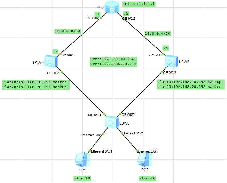
二、实验需求
1.SW1和SW2做VRRP虚拟网关192.168.10.254/24和192.168.20.254/24
2.PC1是VLAN10,使用192.168.10.254网关,PC2是VLAN20,使用192.168.20.254网关.
3.配置静态路由实现全网通(PC1和PC2互通,PC1和PC2能ping通R1上回环口1.1.1.1/32)
三、实验重点:
1. 设置Vlan10的VRRP 的Master在SW1上,设置Vlan20的VRRP的Master在SW2上,因为vrrp默认优先级是100,所以设置101就可以抢占为Master。
2. PC1和PC2获取到的网关要想是192.168.10.254和192.168.20.254,需要有地址池,在里边指定网关,如果不指定那获取到的地址为Master的地址,不是虚拟网关地址。
3. DHCP地址池做好地址排除,因为出现SW1或者SW2故障后,网关切换到另一个是不会出现地址冲突。
4. 静态路由的添加方法。
四、设备基础配置
SW1配置:
sysname SW1
vlan batch 10 20 30
dhcp enable
ip pool vlan10-ipaddress
gateway-list 192.168.10.254
network 192.168.10.0 mask 255.255.255.0
excluded-ip-address 192.168.10.101 192.168.10.251
#
ip pool vlan20-ipaddress
gateway-list 192.168.20.254
network 192.168.20.0 mask 255.255.255.0
excluded-ip-address 192.168.20.1 192.168.20.100
interface Vlanif10
ip address 192.168.10.253 255.255.255.0
vrrp vrid 10 virtual-ip 192.168.10.254
vrrp vrid 10 priority 101
dhcp select global
#
interface Vlanif20
ip address 192.168.20.253 255.255.255.0
vrrp vrid 20 virtual-ip 192.168.20.254
dhcp select global
#
interface Vlanif30
ip address 10.0.0.2 255.255.255.252
#
interface GigabitEthernet0/0/1
port link-type trunk
port trunk allow-pass vlan 10 20
#
interface GigabitEthernet0/0/2
port link-type trunk
port trunk pvid vlan 30
port trunk allow-pass vlan 30
ip route-static 1.1.1.1 255.255.255.255 10.0.0.1
ip route-static 10.0.0.4 255.255.255.252 10.0.0.1
SW2配置:
sysname SW2
#
vlan batch 10 20 30
#
dhcp enable
ip pool vlan10-ipaddress
gateway-list 192.168.10.254
network 192.168.10.0 mask 255.255.255.0
excluded-ip-address 192.168.10.1 192.168.10.100
#
ip pool vlan20-ipaddress
gateway-list 192.168.20.254
network 192.168.20.0 mask 255.255.255.0
excluded-ip-address 192.168.20.101 192.168.20.251
#
interface Vlanif10
ip address 192.168.10.252 255.255.255.0
vrrp vrid 10 virtual-ip 192.168.10.254
dhcp select global
#
interface Vlanif20
ip address 192.168.20.252 255.255.255.0
vrrp vrid 20 virtual-ip 192.168.20.254
vrrp vrid 20 priority 101
dhcp select global
#
interface Vlanif30
ip address 10.0.0.6 255.255.255.252
#
interface GigabitEthernet0/0/1
port link-type trunk
port trunk pvid vlan 30
port trunk allow-pass vlan 30
#
interface GigabitEthernet0/0/2
port link-type trunk
port trunk allow-pass vlan 10 20
#
ip route-static 1.1.1.1 255.255.255.255 10.0.0.5
ip route-static 10.0.0.0 255.255.255.252 10.0.0.5
#
SW3配置:
sy
sy SW3
vlan b 10 20
int eth0/0/1
p l a
p d v 10
int eth0/0/2
p l a
p d v 20
int g0/0/1
p l t
p t a v 10 20
int g0/0/2
p l t
p t a v 10 20
R1配置:
sy
sy R1
int g0/0/1
ip add 10.0.0.1 30
int g0/0/2
ip add 10.0.0.5 30
int lo 1
ip add 1.1.1.1 32
ip route-st 192.168.10.0 24 10.0.0.2
ip route-st 192.168.20.0 24 10.0.0.6
五、重点代码分析
-----------------------------------------
ip pool vlan10-ipaddress
gateway-list 192.168.10.254
解析:地址池中指定网关
-----------------------------------------
interface GigabitEthernet0/0/2
port link-type trunk
port trunk pvid vlan 30
port trunk allow-pass vlan 30
解析:配置pvid为30,是为了数据发出去后剥离vlan30的标签,此接口也可以配置为access接口。
-----------------------------------------
SW1:vrrp vrid 10 priority 101
SW2:vrrp vrid 20 priority 101
解析:
为了让此接口抢占master,将vlan10流量引入SW1的vlanif10接口。
为了让此接口抢占master,将vlan20流量引入SW2的vlanif20接口。
这样也可以起到负载分担的作用,PC1的流量通过SW1转发,PC2的流量通过SW2转发。还能起到互为备份,SW1坏了后,vlan10的流量会到SW2并转发,当然SW2的vlanif10将会变为Master,vrrp具有抢占性,SW1恢复后会抢回来master。
-----------------------------------------
SW1路由表中没有的网段:
1.10.0.0.4/30
2.1.1.1.1/32
SW2路由表中没有的网段:
1.10.0.0.0/30
2.1.1.1.1/32
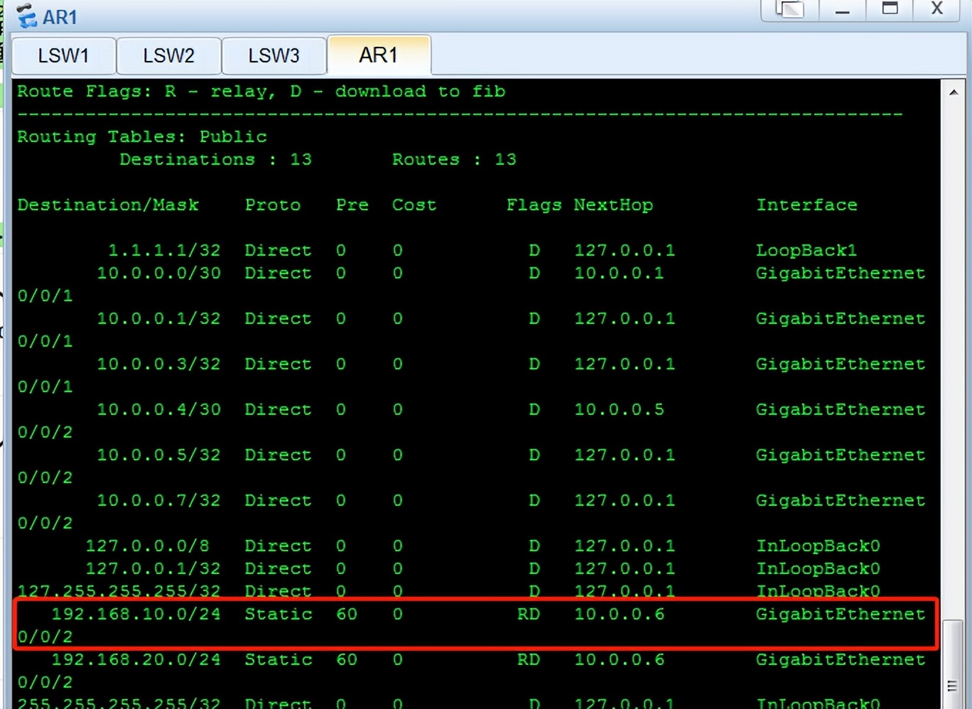
R1路由表中没有的网段:
1.192.168.10.0/24
2.192.168.20.0/24
SW1添加静态路由:
ip route-st 10.0.0.4 30 10.0.0.1
ip route-st 1.1.1.1 32 10.0.0.1
SW2添加静态路由:
ip route-st 10.0.0.0 30 10.0.0.5
ip route-st 1.1.1.1 32 10.0.0.5
R1添加静态路由:
ip route-st 192.168.10.0 24 10.0.0.2
ip route-st 192.168.20.0 24 10.0.0.6
六、 结果截图
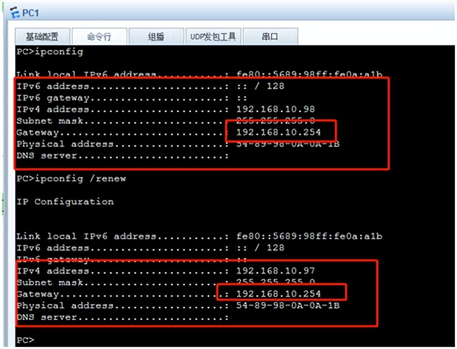
PC1从地址池中获取到了IP地址,排除了192.168.10.101-192.168.10.251,而且获取到网关是虚拟网关,实际网关是192.168.10.253(就是SW1的vlanif10接口地址)
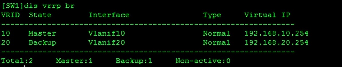
SW1的vrrp,vlan10的Master,vlan20的Backup
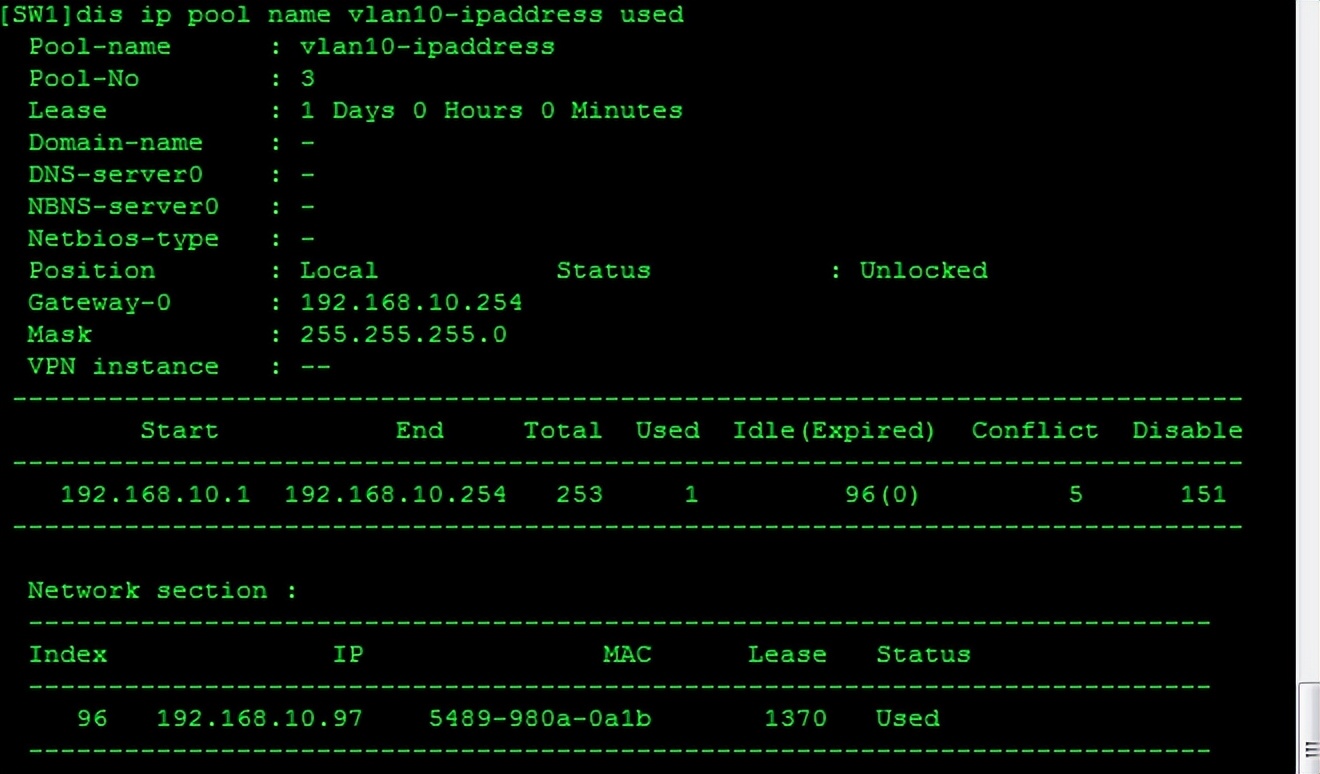
SW1的地址池vlan10-ipaddress的使用情况
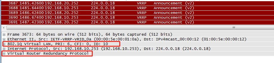
抓包查看VRRP的数据包结构,Ethernet 11 以太网二代,插入了vlan标签,网络层源目IP,VRRP属于网络层协议,VRRP默认是1秒发送一次通告。
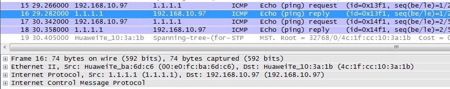
R1和SW1之间抓包,PC1 ping 1.1.1.1,没有vlan标签说明vlan10流量是经过SW1转发的
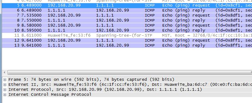
R1和SW2之间抓包,PC2 ping 1.1.1.1,没有vlan标签说明vlan20流量是经过SW2转发的
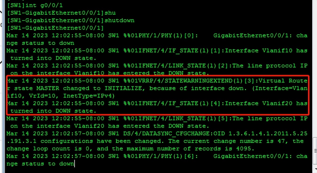
SW1的G0/0/1接口shutdown后,提示vrrp状态down。
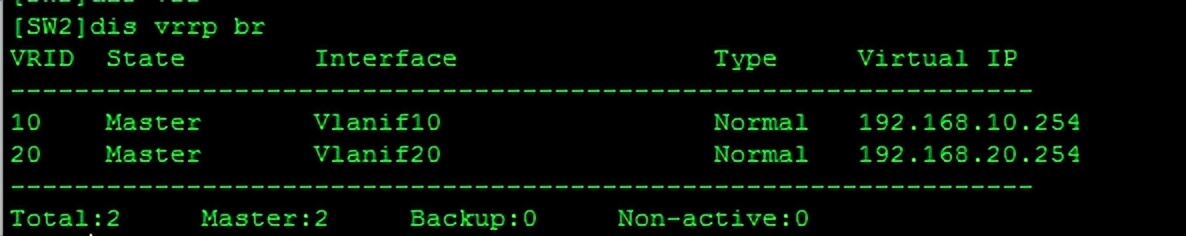
SW1接口shutdown后SW2的vrrp状态。Vlan10的流量已经由SW2转发。

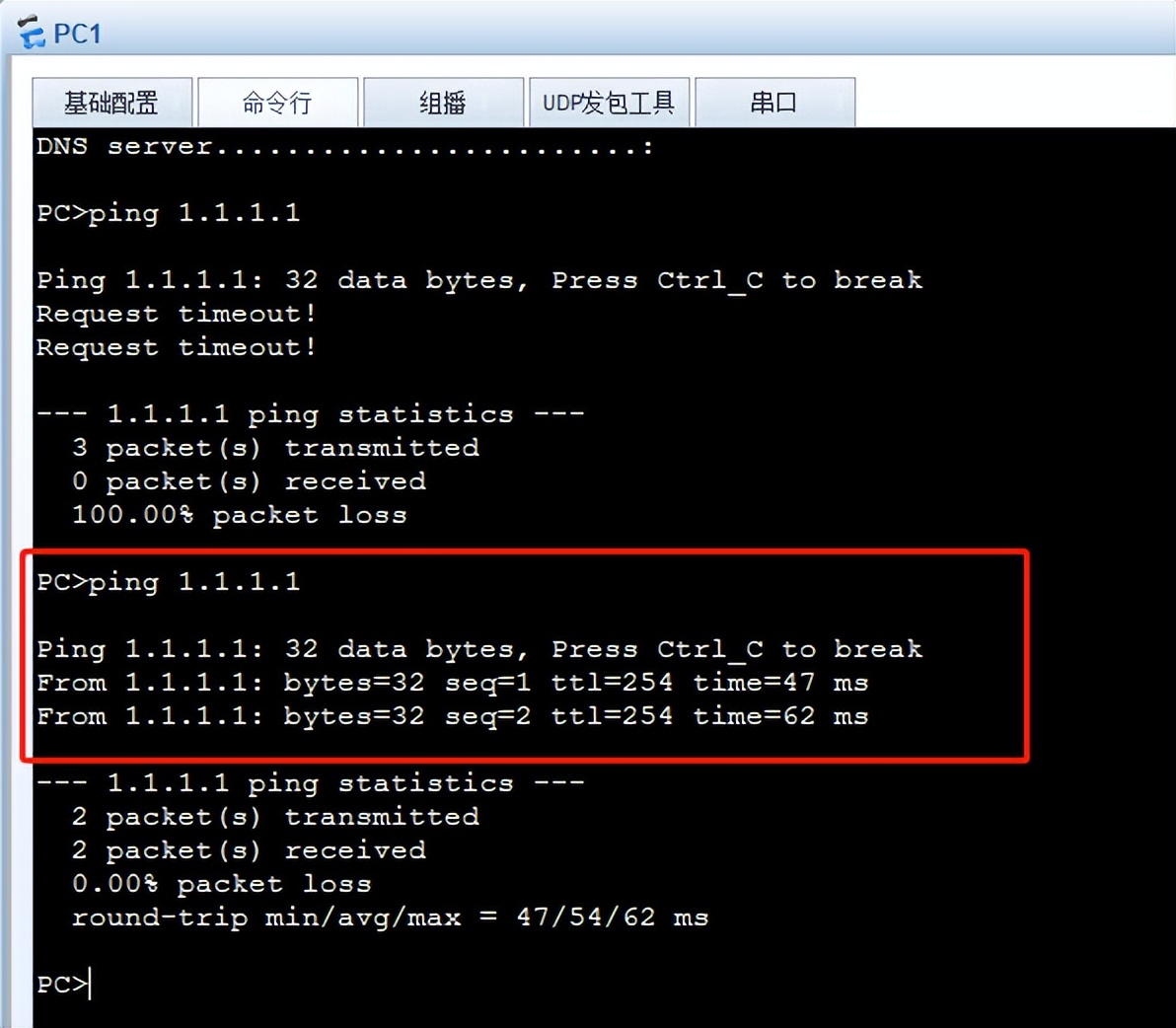
PC1已经拿到了最新的IP地址,那为什么ping不通1.1.1.1呢?因为R1的回程路由ip route-st 192.168.10.0 24 10.0.0.2,所以不通,要手动修改静态路由为:ip route-st 192.168.10.0 24 10.0.0.6